Simple SCR/Triac Tester unit
Universal Rectifiers model # URK230504
Single Phase - SCR
1) Safety First!
2) Turn off all the breakers suppling power to this unit.
3) Remove all the secondary AC tap bars.
4) Disconnect the Positive and Negative cables.
Note: This will help to minimize false tests.
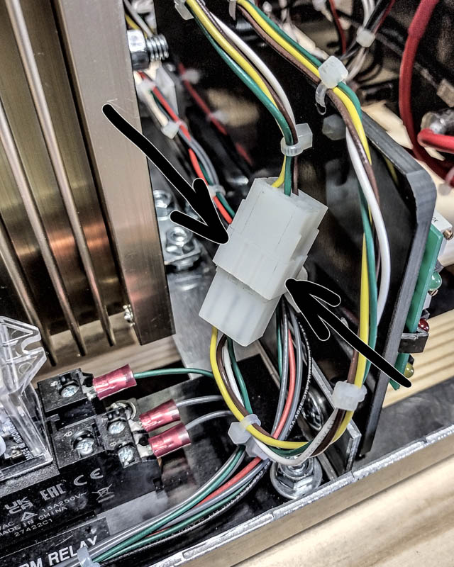
Now that all that is done, we need to find the gate harness going to the rectifier stack.
It’ll look like this.
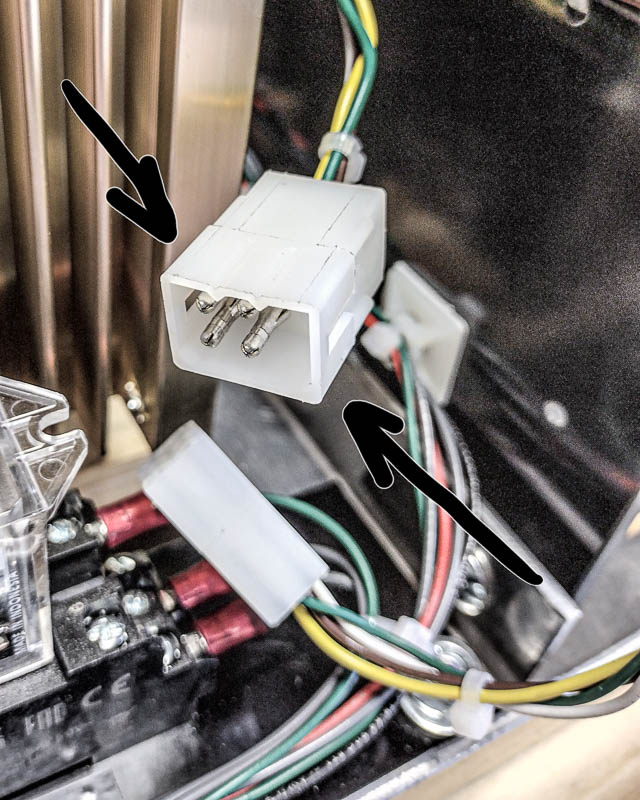
Once you find the harness you need to unplug it.
The end we will be working with is the end with the male inserts as you can see in this photo.
Connect one end of Jumper Lead #1 to Simple SCR/Triac Tester - Cathode Terminal and the other end to the Positive Terminal on the rectifier stack.
Connect one end of Jumper Lead #2 to Simple SCR/Triac Tester - Anode Terminal and the other end to the AC1 Terminal on the rectifier stack.
Note: AC1 Terminal will be the one with the #22-gauge Yellow wire.
At this point check the Test light on the Simple SCR/Triac Tester unit.
If the Test light is not glowing, then proceed to Step 1-2.
If the Test light is GLOWING, the SCR on AC1 heatsink is shorted and should be replaced or if this is a module replace the whole module.
Note: When replacing the SCR or module, be sure to clean off all old diode grease and apply a thin layer for fresh diode grease.
Now connect one end of Jumper Lead #3 to the Simple SCR/Triac Tester - Gate Terminal.
The other end of this jumper will go to the harness that you unplugged and will just touch the pin that is connected to the white wire.
At this point check the Test light on the Simple SCR/Triac Tester unit.
If the Test light is NOT glowing or just flashed as you touched the white gate wire, you should replace the SCR on AC1 heatsink or if this is a module replace the whole module.
Note: When replacing the SCR or module, be sure to clean off all old diode grease and apply a thin layer for fresh diode grease
If the Test light is GLOWING, then proceed to Step 2-1.
Connect one end of Jumper Lead #1 to Simple SCR/Triac Tester - Cathode Terminal and the other end to the Positive Terminal on the rectifiers stack.
Connect one end of Jumper Lead #2 to Simple SCR/Triac Tester - Anode Terminal and the other end to the AC2 Terminal on the rectifiers stack.
Note: AC2 Terminal will be the one with the #22-gauge Brown wire.
At this point check the Test light on the Simple SCR/Triac Tester unit.
If the Test light is not glowing, then proceed to Step 2-2.
If the Test light is GLOWING, the SCR on AC2 heatsink is shorted and should be replaced or if this a is module replace the whole module.
Note: When replacing the SCR or module, be sure to clean off all old diode grease and apply a thin layer for fresh diode grease.
Now connect one end of Jumper Lead #3 to the Simple SCR/Triac Tester - Gate Terminal.
The other end of this wire will go to the harness that you unplugged and will just touch the pin that is connected to the Green wire.
At this point check the Test light on the Simple SCR/Triac Tester unit.
If the Test light is NOT glowing or just flashed as you touched the green gate wire, you should replace the SCR on AC2 heatsink or if this is a module replace the whole module.
Note: When replacing the SCR or module, be sure to clean off all old diode grease and apply a thin layer for fresh diode grease
If the Test light is GLOWING, then these SCR or Module is good.
If you need some extra help just click a link below.

